Network Switching and Routing Using Cisco Packet Tracer
This guide uses Cisco Packet Tracer software to demonstrate switching and routing concepts, allowing users to explore and understand network architectures in a virtual laboratory environment. With this resource, users can design, build, test, and troubleshoot networks, experimenting with different scenarios and configurations in a risk-free setting.
Cross Over Cable
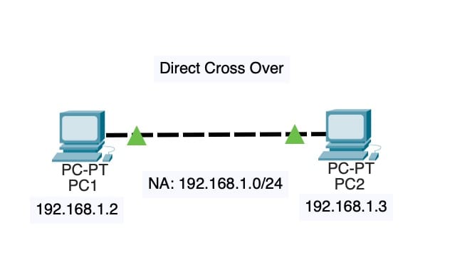
We will set up a simple network with two devices (PC1 and PC2) connected via a cross-over cable using the Cisco Packet Tracer.
Network Address: 192.168.1.0/24
The IP address range for our network is 192.168.1.0/24, which means all devices on this network will have an IP address in the range of 192.168.1.0 to 192.168.1.255.
Set PC1
- Name: PC1
- IP:
192.168.1.2 - Subnet:
255.255.255.0
PC1 is our first device, which will be set up with an IP address of 192.168.1.2 and a subnet mask of 255.255.255.0.
Set PC2
- IP:
192.168.1.3 - Subnet:
255.255.255.0
PC2 is our second device, which will be set up with an IP address of 192.168.1.3 and a subnet mask of 255.255.255.0.
Connect PC1 to PC2 Copper Cross-Over
Now that we have both devices set up, let’s connect them using a cross-over cable.
- Connect the copper cable from PC1’s Ethernet port to PC2’s Ethernet port.
- The cross-over cable is used to connect two devices of the same type (in this case, both are PCs) without the need for a switch or router.
Verifying Connectivity
Once the devices are connected, let’s verify that they can communicate with each other.
- Open up a command prompt on PC1 and ping PC2’s IP address:
ping 192.168.1.3 - You should see a response from PC2 indicating that it is reachable.
- Similarly, open up a command prompt on PC2 and ping PC1’s IP address:
ping 192.168.1.2 - You should see a response from PC1 indicating that it is reachable.
This demonstrates that the devices are able to communicate with each other using the cross-over cable.
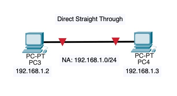
Straight-Through Cable (No Connection)
Step 1: Configure PC3
- Open Cisco Packet Tracer and create a new workspace.
- Drag one PC (PC3) from the “Devices” tab to the workspace.
- Right-click on PC3 and select “Edit Settings”.
- In the Edit Settings window, set the following:
- IP Address: 192.168.1.2
- Subnet Mask: 255.255.255.0
Step 2: Configure PC4
- Drag another PC (PC4) from the “Devices” tab to the workspace.
- Right-click on PC4 and select “Edit Settings”.
- In the Edit Settings window, set the following:
- IP Address: 192.168.1.3
- Subnet Mask: 255.255.255.0
Step 3: Represent the straight-through cable
- Draw a straight line between PC3 and PC4, but do not connect them with an actual cable.
Step 4: Verify that the PCs are not connected
- Right-click on each PC and select “Ping” to verify that they cannot communicate with each other. You should see a failure message indicating that the ping request timed out.
- This demonstrates that even though we have two PCs in close proximity, if there is no actual physical connection between them (i.e., no cable), they will not be able to communicate with each other.
Hub
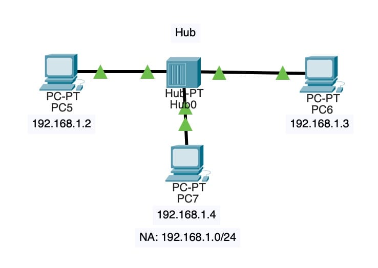
We will learn how to set up a simple network using the Cisco Packer Tracer tool. We will create a hub and connect three PCs (PC5, PC6, and PC7) to it using copper straight-through cables.
Step 1: Set up the Network Address
- Open the Cisco Packer Tracer tool.
- Create a new network by clicking on “File” > “New Network”.
- Set the Network Address to
192.168.1.0/24. This will be our subnet mask.
Step 2: Create PCs and Connect them to the Hub
- Click on “PCs” in the toolbar and create three new PCs (PC5, PC6, and PC7).
- Assign an IP address to each PC:
- PC5:
192.168.1.2with subnet mask255.255.255.0 - PC6:
192.168.1.3with subnet mask255.255.255.0 - PC7:
192.168.1.4with subnet mask255.255.255.0
- PC5:
- Connect each PC to the hub using a copper straight-through cable.
Step 3: Verify the Network
- Click on “Hub” in the toolbar and select “Properties”.
- Verify that all three PCs are connected to the hub and have been assigned an IP address.
- Use the “Network Explorer” tool to visualize the network topology.
Switch
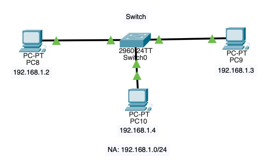
We will learn how to create a basic network with a switch and connect multiple devices (PCs) to it.
Step 1: Create the Devices
- Open Cisco Packet Tracer and click on New to start a new simulation.
- In the Device List window, right-click and select Create Switch once. Name this device as
Switch0. - Right-click again and select Create PC three times. Name these devices as
PC8,PC9, andPC10.
Step 2: Configure the Switch
- Right-click on
Switch0and select Edit. This will open the switch’s configuration page. - Under the General tab, set the following information:
- Device Type: Switch
- Name:
Switch0(or any name you prefer)
- Click OK to save your changes.
Step 3: Configure the PCs
- Right-click on each PC and select Edit. This will open the PC’s configuration page.
- Under the IP tab, set the following information for each PC:
PC8: IP Address =192.168.1.2, Subnet Mask =255.255.255.0PC9: IP Address =192.168.1.3, Subnet Mask =255.255.255.0PC10: IP Address =192.168.1.4, Subnet Mask =255.255.255.0
Step 4: Connect the PCs to the Switch
- Use the Drag-and-Drop feature to connect each PC to
Switch0. - Drag the
PC8icon and drop it onto a port onSwitch0(e.g., Port 1). - Repeat this process for
PC9andPC10, connecting them to separate ports onSwitch0.
Step 5: Verify Connectivity
- Use the Ping feature to verify connectivity between the PCs.
- Select one PC and right-click on it. Select Ping and enter the IP address of another PC (e.g.,
PC8). - If everything is configured correctly, you should see a successful ping response.
That’s it! You have now created a basic network with a switch and multiple PCs connected to it. This is a great starting point for exploring more advanced networking concepts in Cisco Packet Tracer.
Routing
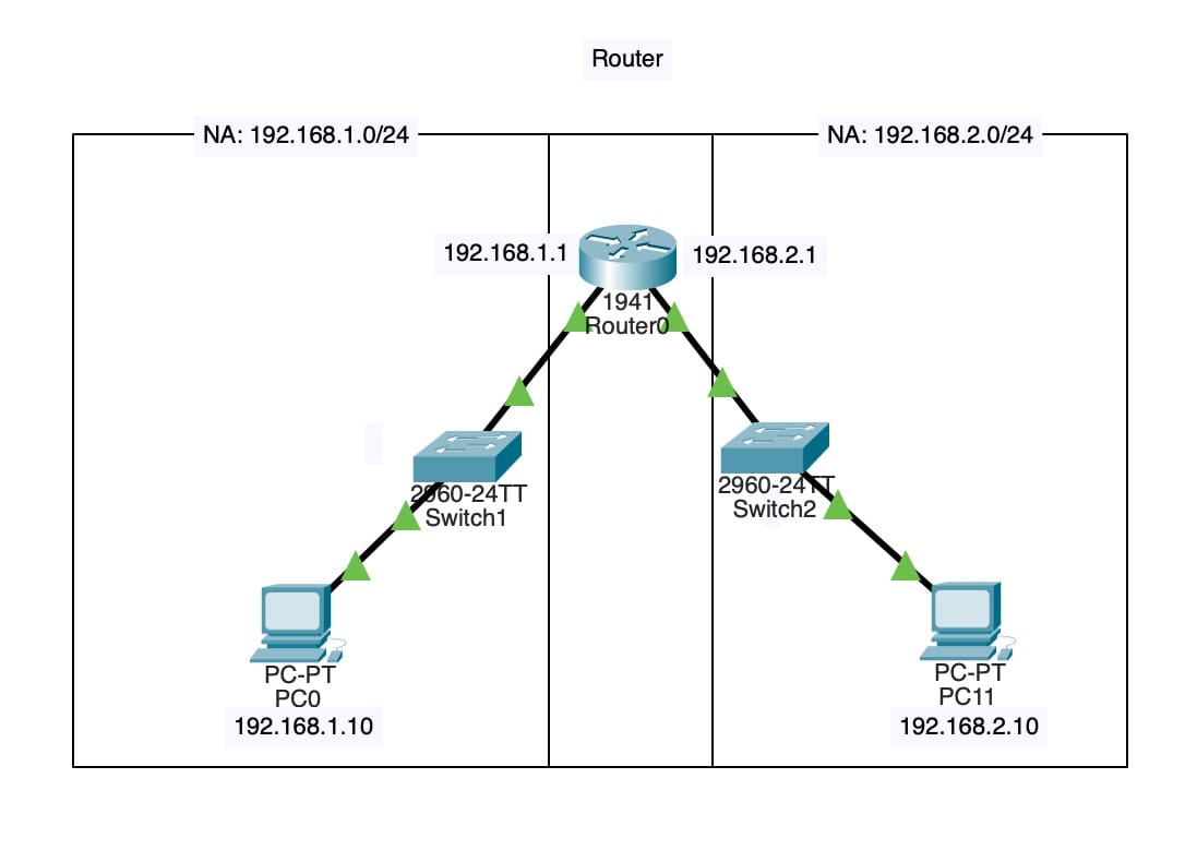
We will demonstrate how to configure a simple network using Cisco Packer Tracer. We will create a network with three devices: two PCs and one router. We will then connect these devices together and verify the routing configuration.
Step 1: Create the Network Devices
- PC0 (IP address:
192.168.1.10, subnet mask:255.255.255.0) - PC11 (IP address:
192.168.2.10, subnet mask:255.255.255.0) - Router0 (IP addresses:
192.168.1.1and192.168.2.1, subnet masks:255.255.255.0)
Step 2: Add Switches
- Switch1
- Switch2
Step 3: Connect Devices Together
- PC0 will be connected to Switch1
- Switch1 will be connected to Router0
- Router0 will be connected to Switch2
- Switch2 will be connected to PC11
Step 4: Verify Routing Configuration
We can verify that the routing configuration is correct. We can see that:
- PC0 has a default route pointing to Router0 (
192.168.1.1) - PC11 has a default route pointing to Router0 (
192.168.2.1) - Router0 has routes for both subnets (
192.168.1.0/24and192.168.2.0/24)
Static Routing
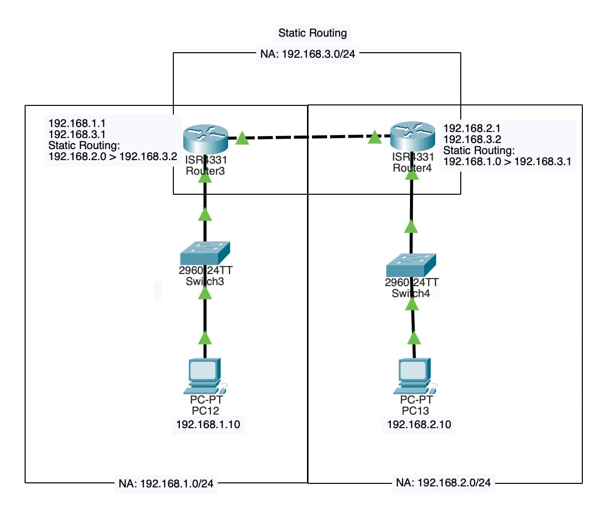
We will be exploring the concept of static routing on Cisco Packet Tracer. We will be setting up a network with multiple devices and configuring static routes to ensure that traffic flows correctly between them.
Network Topology
Our network consists of four devices: two PCs (PC12 and PC13), one router (Router3), and one switch (Switch4). There is also another switch (Switch3) connected to Router3. We will be using the following IP addresses:
- PC12: 192.168.1.10/24
- PC13: 192.168.2.10/24
- Router3: 192.168.1.1/24 and 192.168.3.1/24
- Router4: 192.168.2.1/24 and 192.168.3.2/24
Step-by-Step Configuration
Configure PC12
Set the IP address of PC12 to 192.168.1.10 with a subnet mask of 255.255.255.0.
Configure PC13
Set the IP address of PC13 to 192.168.2.10 with a subnet mask of 255.255.255.0.
Configure Router3
- Set the IP address of Router3 to 192.168.1.1 with a subnet mask of 255.255.255.0.
- Set the IP address of Router3 to 192.168.3.1 with a subnet mask of 255.255.255.0.
Configure Router4
- Set the IP address of Router4 to 192.168.2.1 with a subnet mask of 255.255.255.0.
- Set the IP address of Router4 to 192.168.3.2 with a subnet mask of 255.255.255.0.
Configure Switch3
Connect PC12 to Switch3 and configure Switch3 to forward traffic from PC12 to Router3.
Configure Switch4
Connect Router4 to Switch4 and configure Switch4 to forward traffic from Router4 to PC13.
Now that we have configured the IP addresses and connected the devices, we need to configure static routes on Router3 and Router4 to ensure that traffic flows correctly between them. We will be creating two static routes:
Route 1
From Router3’s 192.168.1.0/24 subnet to Router4’s 192.168.2.0/24 subnet.
- Set the destination IP address to 192.168.2.1.
- Set the next-hop IP address to Router4’s 192.168.3.2.
Route 2
From Router4’s 192.168.2.0/24 subnet to Router3’s 192.168.1.0/24 subnet.
- Set the destination IP address to 192.168.1.1.
- Set the next-hop IP address to Router3’s 192.168.3.1.
RIP Dynamic Routing
Network Topology
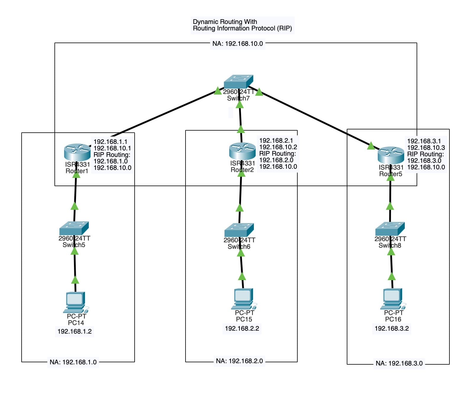
Our network consists of eight devices: four PCs (PC14 to PC16), three switches (Switch5 to Switch8), and two routers (Router1 and Router2). The IP addresses and subnets for each device are as follows:
- PCs
PC14: IP 192.168.1.2, Subnet 255.255.255.0PC15: IP 192.168.2.2, Subnet 255.255.255.0PC16: IP 192.168.3.2, Subnet 255.255.255.0
- Routers
Router1: IP 192.168.1.1, Subnet 255.255.255.0; IP 192.168.10.1, Subnet 255.255.255.0Router2: IP 192.168.2.1, Subnet 255.255.255.0; IP 192.168.10.2, Subnet 255.255.255.0
- Switches
Switch5: connected toRouter1andPC14Switch6: connected toRouter2andPC15Switch7: connected toRouter1,Router2, andRouter5Switch8: connected toRouter5andPC16
RIP Routing
We’ll configure RIP routing on each router to dynamically learn the network topology. Here’s a summary of the RIP routing information for each router:
- Router1:
- 192.168.1.0/24
- 192.168.10.0/24
- Router2:
- 192.168.2.0/24
- 192.168.10.0/24
- Router5:
- 192.168.3.0/24
- 192.168.10.0/24
Step-by-Step Configuration
To configure the network, follow these steps:
- Connect
PC14toSwitch5. - Connect
Switch5toRouter1. - Connect
Router1toSwitch7. - Connect
PC15toSwitch6. - Connect
Switch6toRouter2. - Connect
Router2toSwitch7. - Connect
PC16toSwitch8. - Connect
Switch8toRouter5. - Connect
Router5toSwitch7.
After configuring the network, you can observe that RIP has automatically configured routes between the devices. For example:
- Router1 learns about the 192.168.2.0/24 and 192.168.3.0/24 networks through
Router2. - Router2 learns about the 192.168.1.0/24 and 192.168.10.0/24 networks through
Router1.